
Instrument Approach Plates
The ADF is King!
What an incredible advance the NDB and ADF brought to instrument flying. Their capability went vastly beyond that of the four-course radio range. For the first time, an aircraft could now approach an airfield that it could not see, to a runway that it could not see until very near, and safely land. What a boost that gave to airline on-time performance.
Using the ADF with the NDB, flights can routinely land in prevailing weather of 600 ft ceiling, or less, and only one-mile visibility. Compare that with the nominal 1000 ft ceiling and three-mile visibility requirement of a VFR flight.
The FAA publishes approved instrument approaches for U.S. airports. Aircraft performing instrument approaches must conform to these published procedures. Instrument Approach Plates, as these charts were once officially called but now Instrument Approach Procedures, are published for and named after the Navaid used for the approach. This could be an NDB, VOR, ILS, LOC, RNAV, or GPS. Some approaches also require DME or availability of airport radar.
Only NDB approaches will be discussed here. Master them and all of the other approaches follow easily.
Note that the entire discussion pertains to approaches to airports in instrument conditions. Nowhere is the word "landing" used. That is the pilot's decision within the limits of each published approach procedure.
Yes, despite the emphasis that follows on IFR approaches, aircraft do take off in IFR conditions, too. In the absence of countermanding limits at specific airports, a one or two engine aircraft must have at least one-mile visibility to take off. Aircraft with more than two engines require only a half-mile visibility. In neither case are ceilings specified. Individual airports may have minimum ceiling requirements, with 300 ft. being very common.
A pilot is advised to carefully consider whether to takeoff at these minimums. If the minimum conditions for takeoff are 300 ft. and one-mile, but the only IFR approach procedure requires 500 ft and one-mile, a return to the airport for whatever reason would not be possible.
The Approach Plate
The layout and content of all U.S. approach plates is identical. The easiest way for a flight-simmer to download official U.S. approach plates for free is to go to AirNav.com and enter the ICAO code for the airport of interest (like KBOS for Boston Logan International). Then scroll down the airport page where you will find individual links for each approach plate and departure procedure for that airport.One may also purchase paper versions, eiither bound in volumes or in loose-leaf format, from a multitude of online retailers (search Aviation Charts) or directly from the FAA.
The FAA has divided the U.S. into twenty-four regions as shown in the illustration below. In 2008 the publication price for any one region is $4.60.
In the meantime, click on the Millville NDB approach plate at the top of this section for a full-detailed print.
One brief note on the ILS, the granddaddy of all of the instrument landing systems, before moving on. The ILS, or Instrument Landing System, is a precision approach system. It provides glide-path information in addition to a localizer signal to guide the aircraft to the runway. None of the other approach procedures provide glide-path information and hence are called non-precision approaches. ILS landing minimums are lower than all of the other approach procedures.
Approach Plate Features The most efficient way to explain the features of an approach plate is to work from the top-left to the bottom-right. Following the explanations will be easier, though, if you first print Millville's NDB Runway 14 approach plate.
The Left Header
The left header identifies the City and State where the airport is located, here Millville, New Jersey. Below that, from left to right, is important Instrument Approach information:
- NDB RNB 363 is the Navaid information for this approach ... NDB identifies this as an Approach Procedure using an NDB, RNB is the three-letter identifier of the NDB, and 363 is the NDB frequency, here 363 kHz.
- APP CRS 147° is the Magnetic Course to the runway for this Instrument Approach.
- Rwy ldg 5057 is the available length of runway for landing, here 5057 feet.
- TDZE 81 is the Touch Down Zone Elevation of the runway, above Mean Sea Level, MSL. Here it is 81 feet. The TDZ is that portion of the runway where an aircraft's landing gear normally first contacts the runway when landing.
- Apt Elev 85 is the Airport Elevation at some central point. Here it is 85 feet, or four feet higher than the TDZE of Rwy 14.
The Right Header
The right header identifies the specifics of the approach: The Type of Approach, which Runway, and the Airport Name. This Instrument Approach Plate (IAP) describes the procedure for an NDB approach to Runway 14.
Below that is the airport name, Millville Municipal, followed by its three or four letter airport designator, MIV. The airport name is important for cities with several airports. Be certain you've got the right approach plate in front of you.
In some cases, a runway is not listed in the header, for example, VOR–A. That means that the published approach path is not aligned within 30° of any runway heading. In that case, once the airport is in sight the aircraft must turn to line up with the desired runway.
Second Row – Left Side
The next box down is general flight information related to the airport. Millville Municipal Airport is a small field, two paved runways and no control tower. With only 164 flight operations per day one would not expect many airport remarks. The white "T" in the black triangle indicates that the takeoff minimums are non-standard, that there is a published departure procedure, or some other issue demands the pilot's attention. You will find this information in the front of the paper approach chart booklet, or if you download the approach plates, the departure info will also be linked there.
At Millville, the take-off minimum is 300 ft ceiling and one-mile visibility for all categories of aircraft. A published departure procedure also exists, named LEEAH THREE. Here is the LEEAH THREE departure route description when take-off is from Runway 10 or 14.
Turn left to heading 109° and intercept OOD R–154 (OOD VOR, 154° radial) to LEEAH INT, then via your assigned route ... Maintain 1800 ft., expect filed altitude 10 minutes after departure. The standard takeoff minimums are for aircraft with two engines or less is one statute mile. For aircraft with more than two engines the take-off minimum is one-half statute mile. In both cases, no ceiling is specified.
And finally, the note in the box above ...
When VGSI inop, straight-in/circling Rwy 14 procedure NA at night. informs pilots that if the Visual Glide Slope Indicator (red and white lights adjacent to the runway) are inoperative that straight in or circling approaches to Rwy 14 are not authorized at night.
The center section of the second row defines the Approach Lighting System for the specific runway listed on the approach plate that you are using. Runway 14 at Millville, while lighted for night operations, has no approach lighting system on that runway. So let's take a look at the header information, second row, for the ILS RWY 17 approach at Manchester, New Hampshire, KMHT.

MALSR designates a Medium intensity Approach Lighting System with Runway alignment indicator lights. The dot on the A5 symbol denotes the presence of sequenced flashing lights ... a "Rabbit." Explanations of the various approach lighting systems, and there are many, appear in the Instrument Approach Plate booklet.
Second Row - Right Side
Second Row – Right Side Looking again at the NDB RWY 14 approach at Millville, New Jersey, the right side of the second row of header information provides the Missed Approach Procedure.
Third Row – Communication Frequencies
There are five sections in the row of communications frequencies. They are placed in the order that an arrival aircraft would need them:
- Weather
- Approach Control
- Tower
- Ground Control
- Clearance Delivery
Again we will look at two different examples, Millville, New Jersey and Manchester New Hampshire.
Uncontrolled Field ... No Control Tower
First Millville, an airport with no control tower. From left to right in row three of the MIV NDB Rwy 14 Approach Plate here is what is provided:
 ASOS is Automated Surface Observation System, which continuously measures and broadcasts, minute by minute, the surface weather conditions at an airport. The Millville information is available on 128.125 MHz.
 Approach Control Service is provided by Atlantic City Airport, KACY, 23.6 nm east. Contact Approach Control on 124.6 MHz (327.125 MHz if military).
 Millville Radio is an Automated Flight Service Station, AFSS, connected to a distantly-located service center. File, open and close flight plans, get in-flight weather briefings.
 Pilots use Unicom to contact an operator at the field for airport info; active runway, winds, what sort of operations are currently underway, etc.
 Common Traffic Advisory Frequency ... The frequency to use when announcing your intentions to land, takeoff, enter the traffic pattern, etc. at this uncontrolled field. Other aircraft using Millville will also have their Comm radios tuned to this frequency. The "L" in the black oval indicates that the airport lights can be turned on by the aircraft radio (by clicking the Mic button a designated number of times).
Controlled Field ... Control Tower available
Here is the radio frequency information contained in the five boxes of row three on the approach plate for a field with a control tower. This example is for the ILS Rwy 17 approach to Manchester airport, New Hampshire, KMHT. Again it is in the order that arriving aircraft needs it.
 Automatic Terminal Information Service broadcasts recorded information pertaining to the airport. Typically this includes sky conditions, ceilings, winds, runways in use and any important NOTAMS. ATIS information is updated hourly and the reported name changes each hour. The name is the phoenetic alpahabet, Alpha to Zulu. ATIS ends with the announcement "Inform the controller that you have 'Information Bravo' (or whatever happens to be the current phonetic letter.)
 Approach Control Service, like Millville, N.J., is provided by a distant facility. In this case it's from Boston Logan International airport although Manchester has its own frequency. Boston Logan is 39 nm SE.
 The Control Tower manages and controls all aircraft operations on the active runways including takeoffs, landings, and exit and entry to the active runway while on the ground.
 Ground control manages and controls all aircraft operations on the airport property except on active runways. Principally taxi information and authorization to and from runways.
 Frequency for filing, opening, closing or receiving
a flight plan.
Frequency for filing, opening, closing or receiving
a flight plan.
Plan View Panel
We're back to the NDB RWY 14 approach at Millville, New Jersey. The largest section of an approach plate is the plan view, or "top view" of the approach.
The Plan View Panel has two components: the Minimum Safe Altitude within a 25 nm radius in the lower right-hand corner (can be in any corner) and the plan-view, or overhead view, of the approach in the center.
Minimum Safe Altitude—MSA
The minimum safe altitude—MSA—within 25 nm is shown inside a circle on the plan view. MSA provides 1000 ft. of clearance from all terrain and known obstructions. The 25 nm radius circle is centered on the Navaid used for the approach. For Millville that's the RNB NDB, and for Manchester it's the MHT VOR. RNB and MHT are the three-letter designators for the respective Navaids.
Note that the center symbol in the MSA diagram corresponds to the type Navaid used for the approach, or will be a waypoint symbol if flying a GPS approach.
If you are within 25 NM of Millville, you must fly at or above 2100 ft to clear all obstructions by at least 1000 ft. This MSA is independent of your magnetic heading towards RNB NDB.
More than one MSA can be designated for any given approach Navaid, as the Manchester diagram shows. Here are the three MSAs for the MHT VOR:
- 3500 ft if approaching from the North, magnetic course between 046° and 226°.
- 2600 ft if approaching from the East, magnetic course between 226° and 316°.
- 2000 ft if approaching from the South, magnetic course between 316° and 046°.
Approach—Plan View
Centered in the plan view are the "horizontal" details of the instrument approach. Horizontal details mean that no altitude information can be obtained from this portion of the plate. That information appear in the profile view, in the next-described panel.
The plan-view features are explained below in the order that a pilot confronts them. Letters "A" through "K" defines this sequence. Click on the image above to print the approach plate imprinted with these identifying letters to follow the explanation.
- Identify the NDB—be certain that you are approaching the correct beacon. Frequency indication on the receiver is not sufficient because LF beacons can have great range. Listen for the ident Morse code as shown in the Navigation box. The IAF at the top of the box means that this Navaid is the Initial Approach Fix for this instrument approach. All approaches start somewhere, and that place is the IAF.
- The Navaid here is Rainbow NDB, ident RNB. Approach the airfield by tracking to the NDB.
- On reaching the IAF, turn OUTBOUND from the airport. In this case, the track (compensating for wind) should be 327°.
- Track outbound from the IAF for two minutes, then start the procedure turn. Here it is a left turn to 282°. Note that the line with a half-arrow head indicates that a procedure turn is a mandatory part of the approach procedure.
- Proceed on the 282° heading for a minute or so, then turn AWAY from the airport to the reciprocal heading of 102° to return back to the approach course to the field.
- As the ADF indicator nears the 147° bearing to the NDB, turn inbound, right in this case, and track to the NDB on that bearing.
- Continue inbound until the field and runway 14 is in sight. The miniature airport plan "G" accurately portrays the runway layout in relation to your inbound track.
- If the runway is not in sight when it should be, a missed approach is mandatory. "H" shows that a right turn is required to perform a missed approach.
- The missed approach procedure generally sends the aircraft to the Navaid and into a holding pattern to await further instructions from ATC. "I" shows the holding pattern and the proper headings. It also shows, in this case, that the holding pattern requires right turns.
- Before beginning the approach, take note of the obstructions. By now you are aware that antenna towers seem to cluster near airports. Know generally where they are and their height.
- The circle surrounding the plan view of the approach procedure is 10 nm in radius, centered on the Navaid. You are expected to remain within this 10 nm. distance from the beacon while performing the approach. i.e., don't fly a 20 nm outbound leg, or 15 nm after turning into the procedure turn. You only own the airspace within the 10 nm radius circle.
OK, I give up—what's a procedure turn?
Looking again at the approach plate, your flight path brings you to the beacon, RNB, then you fly outbound from the beacon, away from the airport and runway. Obviously you have to get turned around to return to the airport, and the procedure turn is a standardized way of doing that. It's common to execute the procedure turn about two minutes out from the beacon. That time is flexible, but too little rushes you too much on the return to the beacon and too long may take you outside the mandatory 10 nm. radius that you must remain within.
There's an unpublicized hazard, too, with a procedure turn that begins a loooong way out from the beacon. That's the bevy of pilots of high-performance aircraft asking to see you, the ones that you delayed while you moseyed that long distance back to the beacon at a nice leisurely pace.
The procedure turn begins with a 45° turn away from the outbound track. Fly that heading for a minute or so, nothing hard and fast about that time, then execute a 180° turn away from the airport to return to the desired bearing to the beacon.
When you intercept the desired inbound bearing to the beacon, actually just shortly before that point, you make another 45° turn, this time toward the airport, nicely rolling out on the specified track back to the beacon.
The approach plate defines the direction of the procedure turn from the outbound track. There is no freedom in that: what the chart shows is mandatory.
Approach Profile
As just seen, the plan view on the approach plate gives no altitude information. That information is on the profile view.
Considering the approach again, the aircraft flies outbound, tracking 327° from the NDB. Notice the underlined 2000 in the profile view. That indicates that the aircraft may not descend lower than 2000 ft MSL while outbound and in the procedure turn.
Once the aircraft is inbound, tracking 147° to the beacon, it may descend further, but no lower than 1300 ft. until it reaches the beacon, also referred to as the FAF or Final Approach Fix. From that point it may begin its descent to the MDA, or Minimum Descent Altitude, which is discussed on the next part of the approach plate.
The heavy line to the right of the beacon signifies the runway. Here, it is 3.7 nm from the beacon, a crucial number to know in a non-precision approach, where distance is gauged by time.
How low can you go? What are the minimum visibility requirements? Read on.
Minimums
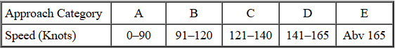
Landing minima are established for six categories of aircraft; ABCDE and COPTER. An aircraft fits into one category or another based on its maneuvering speed. Maneuvering speed is defined as 1.3 times the stall speed at maximum gross weight in the landing configuration. The table below identifies the Category vs. Maneuvering Speed.
The next two rows list the minima for the two possible types of landing with this procedure: Straight in to runway 14 (S–14), or Circling to land at any of the other available runways. A Straight landing is defined as one where the approach course is aligned within 30° of the runway heading.
The straight-in landing minima at Millville for runway 14 is 560 ft. Minimum Descent Altitude (MDA) and one statute mile reported visibility for Categories A and B aircraft. The MDA remains the same for C and D, but the visibility minimums increase to 1¼ and 1½ statute miles respectively.
MDA is exactly as the words say. The aircraft may not descend below the Minimum Descent Altitude during an approach unless the approach-end of the runway is firmly in sight, and a safe, normal visual landing can be made. No diving to the runway hoping to touchdown on the last quarter of its length.
Ignore the numbers in the parenthesis; they apply to military aircraft only. The small numbers just before the parenthesis is the actual height of the MDA above the airport. This may not be the mathematical subtraction of ceiling and field elevation, because field elevation and airport height can differ by several feet.
Note that some of the landing minima for a circling approach are slightly higher than for a straight-in approach.
Airport Plan View
This view gives the pertinent details of the runways; their length and width, and the runway numbers. Note the "TDZE 81" for Runway 14. That is the Touch Down Zone Elevation for Runway 14. Recall in the minimums table that for the S–14 approach with an MDA of 560 ft, the height above the airport was shown as 479 ft? That was obtained by subtracting the 81 ft TDZE from 560 ft MDA.
Recall also on the plan view of the approach, that two runways were in the little diagram at the end of the approach arrow? The airport plan view shows that runways 10–28 and 14–32 are available.
The airport plan view also reminds the pilot that Rwy 14 is 3.7 nm from the FAF, Final Approach Fix, which is the NDB, and that the approach course is 147°.
At the bottom of the view is the runway lighting information. Here MIRL, Medium Intensity Runway Lights, are available on both runways and are pilot controlled.
The Black circle with a white "A5" inside of it near Rwy 10 indicates the type of lighting. A white letter in a black circle denotes that the lights are pilot controlled. The dot at the top of that black circle indicates sequenced flashing approach lights–called "the rabbit" by pilots because they chase it down to the end of the runway.
If the airport is large, its plan view occupies an entire page of the approach plate booklet.
Time from FAF to MAP
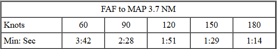
It would be nice if our aircraft, considering any wind component, approached the MAP at a speed exactly listed in the table. Seldom happens, so interpolation is needed. Assume you approach in your Barn Burner at 75 knots, midway between two entries in the table. Recalculate for your 75 kt approach speed, 2 min., 58 sec., and jot that time down on your clipboard so that it will be available when you run the approach. Don't want to be doing those calculations at the final moments of the approach.
It's time to fly the approach. Click on the NDB off Airport button to get into the soup and see if you can find the runway.
Site best viewed at 600 × 800 resolution or higher.
© 1999 – 2008, Charles Wood.